Thursday, November 2, 2023

Salt Lake Temple, July - October '23

This is a diagram from the Temple Square website. Most of these photos involve this area of construction. The diagram shows the base isolators either side of the original temple foundation. Above the base isolators is the reinforced concrete transfer beam. The interior and exterior transfer beams are connected to the pipe beams which are already in place beneath the original foundation. The transfer beams will be tied together with tension cables running through the pipe beams. Cable sleeves will be placed in the transfer beam formwork. After it is cast, the cables will be run through the sleeves and tensioned. After tensioning, the sleeves will be filled with grout.
Anyone curious about this process should read the linked page about the renovation. You'll certainly understand these posts more having read it.
templesquare.org

In this photo from July, all the base isolators have been placed on this side of the temple exterior. Plates are bolted to the tops of the isolators off of which large steel shear pins protrude upwards. These will make sure the tops of the base isolators move with the concrete transfer beam which will move with the temple in an earthquake. The base isolators are surrounded by foam blocks which will be removed once the concrete transfer beam is poured and cured.
The soil above the two larger pipe beams running beneath the temple walls has been removed. It's hard to tell, but I believe the interior and exterior transfer beams will be connected through this area, but I'm not sure.
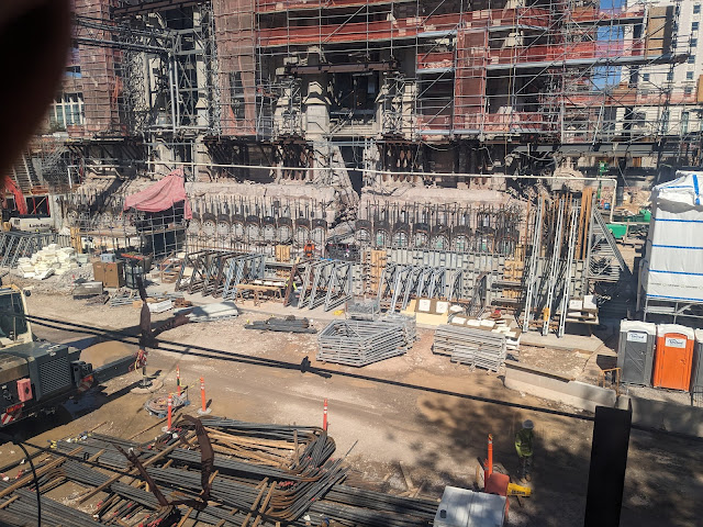
Formwork and rebar for the transfer beam begins to be assembled at the bottom right. This is the Southwest corner of the temple.

Formwork and rebar for the transfer beam is progressing. As a reminder, the ends of the tension cable sleeves is visible in the ends of each pipe beam. These sleeves will be extended through the transfer beam. The temple will sort of float above empty space, with these tension cables helping split the load to the inner and outer base isolators.

Spire stones at the Northwest corner are being replaced after a long absence. All the temple spires have been reinforced with structural steel throughout, up to the very tip. A temporary crane sits atop the structural steel.

Something really fascinating is happening. A bit to the right of center, you can see plywood sheets with squares of styrofoam attached to them. I could be wrong, but I believe these are formwork negatives for the transfer beam tension cables. Notice how these foam blocks are at different angles. I think that the sleeves for the tension cables, once they come out of the pipe beams, will fan out in different directions. The ends of these sleeves will intersect with the face of the transfer beam at odd angles, so I think these blocks will form out a flat opening perpendicular to the ends of the cable sleeves. Pretty cool stuff.

Vertical drilling through the temple walls continues. The white structure to the right of the umbrella is a core drill. Tension cables or steel bars will run through walls the entire height of the temple, tying every block down to the foundation with tension.

Formwork and rebar placement continues. More foam blocks are visible. As you can see, some are at a slight angle, some are steep. It looks like some kind of steel ring is placed on the face of the foam block. These will be cast into the concrete transfer beam.
A pile of beefy rebar sits at the bottom of the picture. These transfer beams have to hold the entire weight of the temple, so the reinforcing steel is immense.

Barely visible at the center of the photo, just above the formwork panel, we can see some of the tension sleeves. It looks like they bend out horizontally at their middle, but they perhaps may not be in their final position. Concrete is weak in tension, so the rebar and many tension cables will hold it together.

I can't explain this one. Atop the larger pipe beam running beneath the temple - it looks like there are sections of similar pipe stacked on top of it. I'm not sure what this is or its purpose.
More base isolators are stacked on the left. Near the bottom right we see rebar rings. I assume these will wrap around the tension sleeves.

A closer look at the large pipe beam. Not sure what's stacked on top of it.

The Southwest visitor pavilion takes shape. These pavilions are much larger than I anticipated them to be.

Some tension sleeves can be seen above and to the right of the workers at the center of the photo. It looks like these are sitting waiting to be put in their proper orientation. It's possible though that there will be tension cables running the length of the beam.

The amount of rebar in these beams is staggering.

The West side of the Southwest visitor pavilion. Steel embed plates are affixed to the upper formwork. I assume roof structure will hang off of these plates.

A view of the Northwest patron entrance building. Foam archways provide a negative around which concrete is poured.

As of the end of October, the transfer beam formwork nears completion.

Northwest of Temple Square in a work zone sits a mock-up for the concrete-window interface. This is probably for the south visitor pavilions. Some kind of pressure test was done to certify the windows meet the requirements, and approval stickers are placed on the windows.

This is the part I'm really geeking out about. This is a mockup for studying the interface of the movable temple structure with the surrounding static structure at ground level. In the event of an earthquake, the temple may move up to 5 feet in any direction, but the surrounding ground will be stationary. There has to be some kind of mechanism to allow for movement while still being safe for anyone standing near the temple. I believe this is the mockup for that system.
The wall in this photo represents the stationary wall surrounding the temple. In the diagram at the beginning, this wall isn't shown, but imagine a concrete wall at the left edge of the diagram. This wall is stationary and affixed to the earth.

It's difficult to see with the wood railings, but on a lip in that exterior wall rests a large steel pan (painted white). The left edge of this pan has a beveled front edge and rests on top of (I assume) the concrete transfer beam or another concrete slab higher up. The beveled front edge can slide up a small metal ramp in the event of seismic movement of the temple.

When the temple-side edge slides up the ramp, the steel pan rotates like a hinge on the lip of the stationary wall.

Another shot of the entire mockup. Perhaps I'll make a diagram of how this works for clarity.

I believe the steel pan will be filled with pavers or whatever kind of decorative concrete work surrounds the temple. Most people will never know that what they're walking on is integral to the seismic protection system for the temple.
Here you can see how the left edge of the pan can slide up metal inclines to allow the concrete beneath to move left or right.

I love this kind of stuff. I can't wait to see how this looks when the project is finished.

Another look at the Northwest patron entrance building.

Much of the solid wall around Temple Square is being replaced with iron fencing. It will be much more inviting and open.
Thousands of people are working to renovate the Salt Lake Temple and Temple Square. I'm grateful for their work.


No comments:

Post a Comment